Difference between pages "Template:MicroUSB-OTG-port" and "Android Buttons"
(Difference between pages)
Jump to navigation
Jump to search
(Created page with "<h1>Using microUSB OTG port and SAM-BA</h1> To check if the first stage loader from CPU ROM starts, connect pico-SAM9G45 board to your computer through the microUSB OTG port a...") |
m |
||
| Line 1: | Line 1: | ||
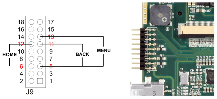
| − | < | + | Using J9, you can enable the actions for the '''HOME''', '''BACK''' and '''MENU''' buttons.<br> |
| − | + | - Pin 11(TXD2) is for the '''BACK''' button,<br> | |
| − | + | - Pin 12(SPI1_SCMK) is for '''HOME''' button,<br> | |
| − | + | - Pin 13(RXD2) is for the '''MENU''' button.<br> | |
| + | - For Ground you can use a single pin. Pin 5 or pin 6.<br><br> | ||
| + | Please see the images bellow.<br> | ||
| + | [[File:J9-connector.jpg|link=]]<br> | ||
<br> | <br> | ||
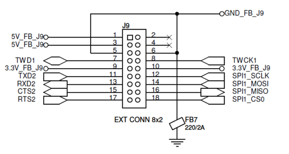
| + | '''J9''' connector schematic:<br> | ||
| + | [[File:pico-SAM9G45-J9-schematic.jpg|link=]] | ||
Latest revision as of 07:59, 20 October 2020
Using J9, you can enable the actions for the HOME, BACK and MENU buttons.
- Pin 11(TXD2) is for the BACK button,
- Pin 12(SPI1_SCMK) is for HOME button,
- Pin 13(RXD2) is for the MENU button.
- For Ground you can use a single pin. Pin 5 or pin 6.
Please see the images bellow.
J9 connector schematic: